The fluid model of the spring-loaded liquid jet injection separately considers the injection portion of the spring-powered liquid jet injection system, and after one-dimensional treatment, the physical model of the liquid jet injection is as shown. Where xp(t) is the displacement of the piston, L is the initial length of the injection chamber fluid, hp is the distance between the core rod and the inner wall of the chamber, A0 is the cross-sectional area of ​​the orifice, and Ap is the cross-sectional area of ​​the piston.
p(t) is the pressure of the fluid in the cavity (relative to atmospheric pressure), and p2 is open to the atmosphere. When the core rod moves inward at a speed u(t), the fluid in the ampoule is extruded at a high pressure at a high pressure; at the same time, the shear flow directed to the sealing ring cannot pass through the seal, forming a strong pressing pressure p3 (t ).
Modeling of the injection injection process BakerSanders simplified the liquid flow into a quasi-equilibrium process, establishing a mass conservation equation and a force balance equation for the fluid and the piston respectively. The resulting relationship between the outlet pressure of the liquid orifice, the size of the piston, and the displacement and area of ​​the piston is Dp(t)dt=(B+p(t))dxp(t)dt-BAOAp2p(t)Ï0L-xP(t)(1) The force balance equation of the piston is d2xp(t)dt=k(x0-xp (t)-s)mp-App(t)mp-Ff(t)mp(2) where B is the concentrated elastic modulus, Ï0 is the initial density of the fluid in the cavity, and Î”Ï is the density increase of the fluid during the injection The quantity, k is the spring stiffness coefficient, x0 is the compression amount after the spring is reset, s is the collision gap, Ff(t) is the resistance of the sealing ring, and mp is the mass of the piston.
Calculation of the resistance of the seal ring The resistance of the seal ring is divided into two parts, one part is the pressure formed by the seal ring to block the liquid fluid, and the other part is the friction between the seal ring and the barrel wall. The moving piston seal and the fixed cavity wall form a fluid film with a sealing end face, and the membrane pressure distribution can be described by the classical Reynolds equation.
First, calculate the liquid pressure to be sealed after the piston rod is moved. During the movement of the mandrel, the fluid flow rate Q(t) passing through the gap at any time can be obtained by the height integral of the velocity versus the gap Q(t)πD=∫h0u(t)dy=u(t)h02(3) Where h0 is the film thickness at the maximum pressure and D is the inner diameter of the cavity.
From equation (3): h0=2Q(t)πDu(t)(4) Substituting equation (4) into the Reynolds equation, the pressure gradient dp3(t) at the wedge between the seal ring and the cylinder wall can be obtained at any time. Dx=6μh-h0h3v=12μh3u(t)h2-Q(t)πD(5) where μ is the dynamic viscosity of the fluid and h is the film thickness at x in the corresponding wedge region.
It can be known from the motion process that the fluid is blocked during the movement of the core rod, Q=0, so that dp3(t)dx=6μu(t)h2(6) is integrated in the x direction for the equation (6), and the average extrusion is obtained. The pressure p3(t) is p3(t)=∫d20dp3(t)dxdx≈p(t)+126μu(t)h2md2(7) where hm is the film thickness at the wedge entrance.
Secondly, the frictional force of the contact surface under the liquid pressure is calculated after the movement of the piston core rod.
According to the above analysis, the pressure ps(t) at the sealing surface of the sealing ring at a certain compression ratio (such as 18%) at the liquid pressure of p3(t) is: ps(t)=pc+ktp3(t)(8) In the formula, pc is the average pressure on the contact surface of the sealing ring under the action of no liquid pressure, and the finite element analysis shows that pc≈315MPa<5>; kt is the pressure transmission coefficient of the sealing ring. , kt is close to or equal to 1<6-7>; ktp3(t) is the contact pressure transmitted by the sealing ring to the contact surface through the sealing ring.
Then the frictional force at the contact between the sealing ring and the cylinder wall is f(t)=θF(t)==πDbθ(pc+p3(t)) (9) where F(t) is the contact pressure of the contact surface, θ It is the friction coefficient of the contact surface, and b is the contact width. When calculating, take θ=012, b≈1mm. The total resistance of the seal is Ff(t)=p3(t)S2+f(t)=p3(t)πDhp+f(t)(10) where S2 is the liquid extrusion pressure acting on the seal The area on the circle.
Calculation method and measurement of jet stagnation pressure Substituting equation (10) into equation (2) forms closed differential equations (1) and (2), which can be decomposed into three linear differential equations. The differential equations can be solved by the Runge 2 Kutta integral method.
The initial conditions need to be set when solving the differential equations. In the actual injection injection, when the switch is triggered, there is often a gap between the striker and the piston core to ensure a certain impact, which affects the flow and pressure dynamic distribution of the liquid. Because of the linkage between the piston and the liquid, the impact process of the ram increases the complexity of the problem. In the mathematical processing, the result of the impact process of the ram is simplified as the piston has a certain initial velocity, and the initial velocity increases as the collision gap increases. . If there is no collision gap, set the initial velocity of the piston to 10 μm/s (set to a minimum value). Other initial conditions are: the initial displacement of the piston is 0, and the initial pressure of the liquid is 0 (relative to atmospheric pressure).
A schematic diagram of the test device is tested. After the signal is injected by the data acquisition software, the experimental data of the injection pressure is obtained by software processing, and the average stagnation pressure of the jet is derived according to the diameter of the nozzle. See the literature for details.
Calculation and experimental results In order to facilitate the comparison of the calculation results with the experimental results, the parameters used in the calculation process are selected from the parameters used in the experiments. The jet injection system used in the experiment was a self-made jet injection system <8>. The calculations and experiments were divided into two groups: the first set of fixed spring coefficients and the piston area, using different liquid doses; the second set of fixed liquid doses and piston areas, using different spring coefficients. In the first group, the corresponding collision gap also changed due to the change in the liquid dose. In the calculation and experiment, the collision gap of 013mL is set to 0, that is, when the liquid dose is 013mL, the impact head and the piston core rod just collide, and as the liquid dose decreases, the collision gap increases.
The relationship between the stagnation pressure and the time obtained by the experiment at 013 mL was calculated. Among them, the dynamic relationship of the first 100ms after the start of the injection is the dynamic relationship of the first 10ms. The values ​​of the parameters used in the calculations and experiments are found in the corresponding parameter values ​​of the 013 mL column. It can be seen that the average value of the stagnation pressure in the first 5 ms is about 10-15 MPa, and it drops to 0 at 100 ms. The injection injection has similar injection characteristics: one or several high pressures exist in the first 1-5 ms. The resistance of the seal ring under the action of high pressure liquid after the impact pressure is analyzed in detail. Under the condition of the system parameters of the self-made jet injector, the equation is solved by the numerical calculation method, and the calculated relationship between the stagnation pressure and the time is consistent with the experimental measurement results. In addition, the maximum injection stagnation pressure at different doses and different spring stiffness coefficients was calculated by the given model and compared with the experimental results. The experimental results verify the correctness of the model.
The power driving method of the injection injection system is not limited to a spring, but may also have a compressed gas, a piezoelectric ceramic, an electromagnetic force drive, or the like. If the spring force in equation (2) is replaced by the displacement, the model can also be applied to other injection-injection systems. In addition, the final injection effect of the jet injection system also depends on the condition in which the jet enters the skin, ie, the mechanical properties of the skin. Therefore a model that fully describes the jet injection process should include the process of jetting into the skin.
Philizon enjoys a high reputation in grow led lamp and led aquarium light fields throughout Europe and America,Philizon also insists on taking high technology to design the newest&best led Grow Light and aquarium light constantly as the market request. Our R&D team with more than 10 people has rich experience in appearance design, electronic structure,heat dissipation simulation analysis,optical lens design,light control system etc.Most of our hydroponics full spectrum led grow lighting and Led Fish Tank Lights are private modules,we have 10 more design patent and utility model patent till now.
Our Led Fish Tank Lights are popular in led market,cause its elegant outlook and its high quality and competitive price.
Item Display
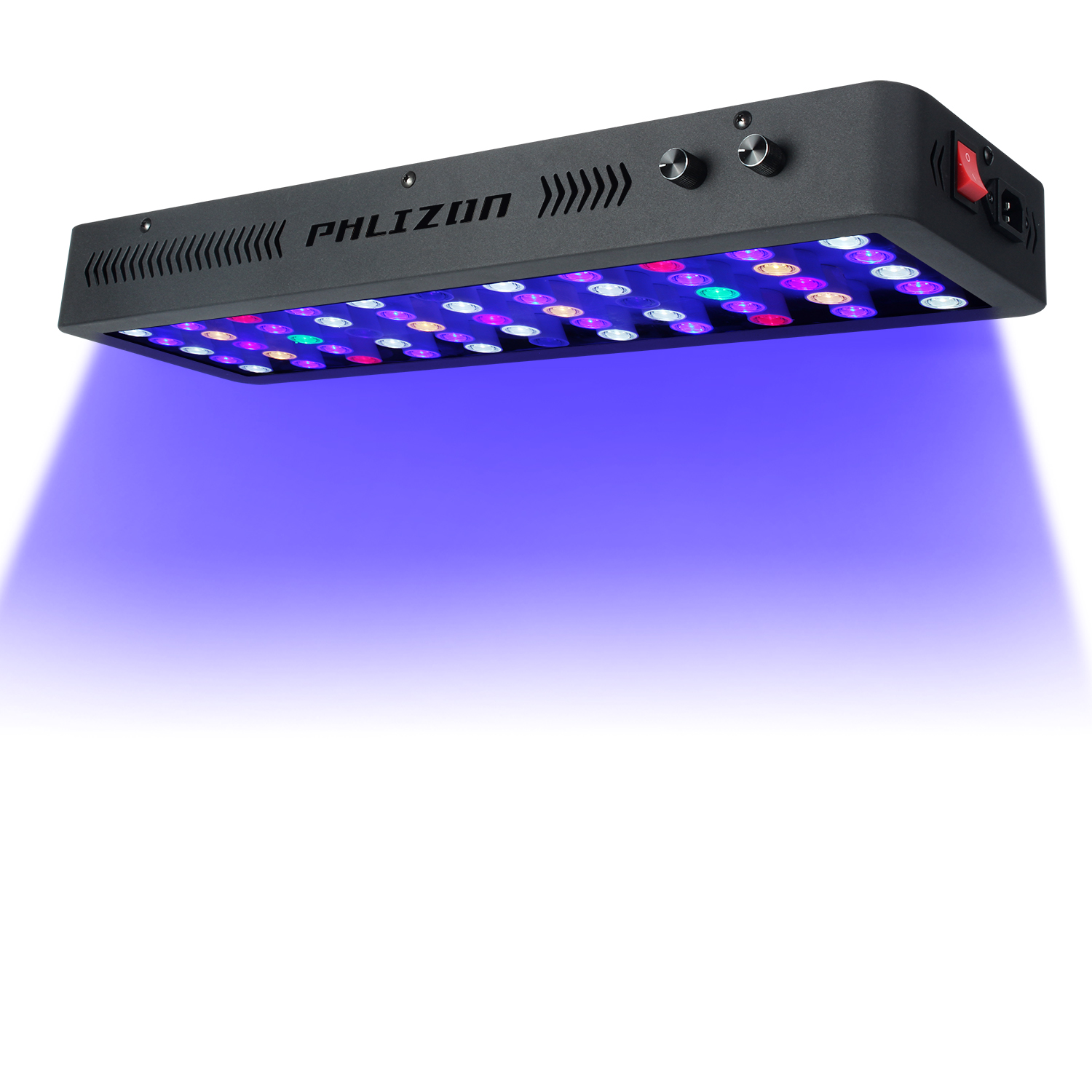
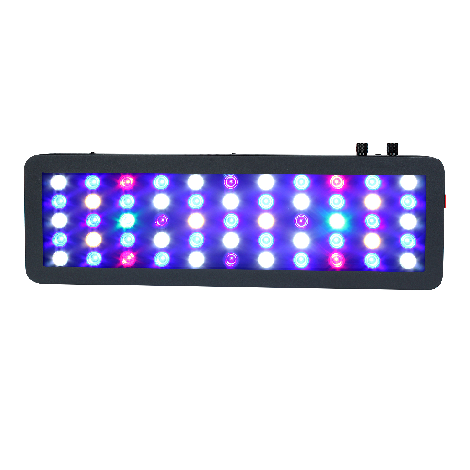

Key Features
1.The lifespan is over 50000 hours,low maintenance costs.
2.Energy conservation,saving over 80% energy than the traditional HPS.
3.High light efficiency,90% of the light will be absorbed by the aquatic plants,while just 8%-10% to the HPS.
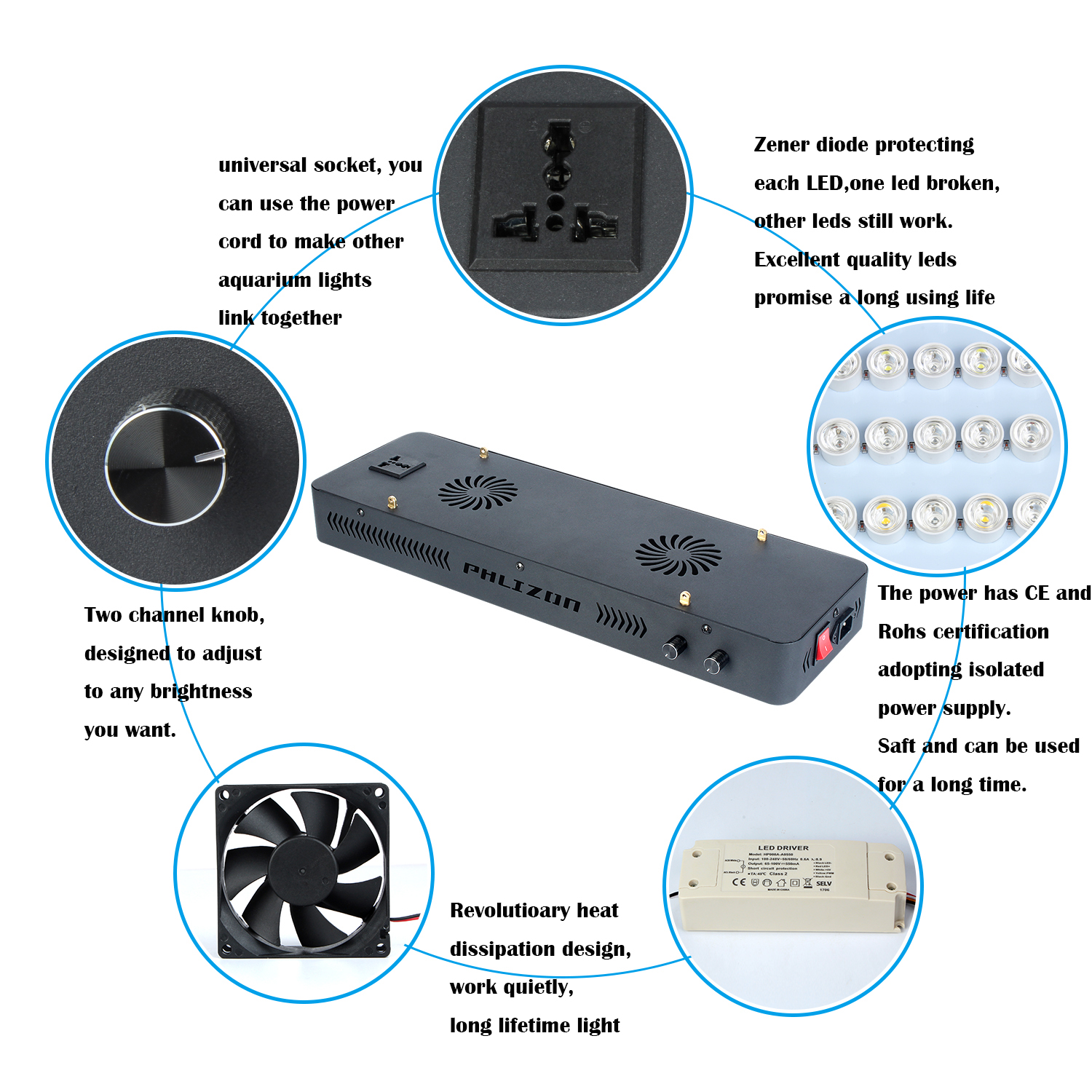
4.Build-in cooling system,could solve the heat dissipation excellently.
5.Built-in power supply, CE approved, No setup required, just simpler and safer plugs directly into AC85V-264V, no reflector & ballast needed.
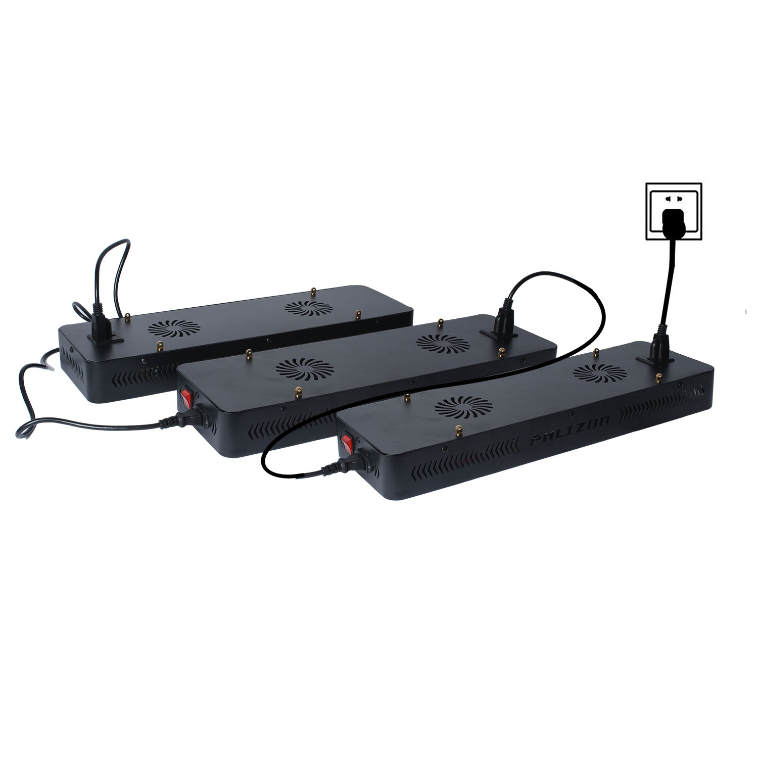
Convenient in using lights at the same time.
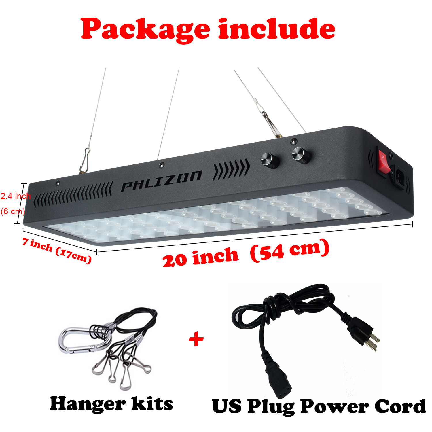
Package Include
1 X Free Hanging Kit
1X Free Power Cord
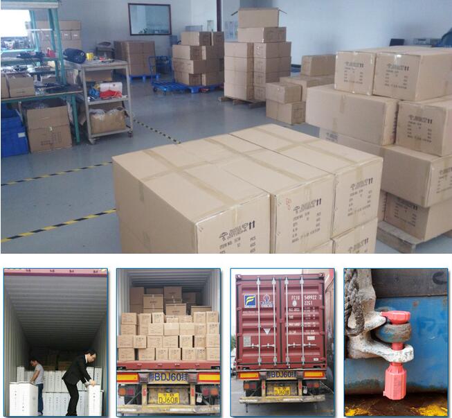
Quality Control systems and after-sales
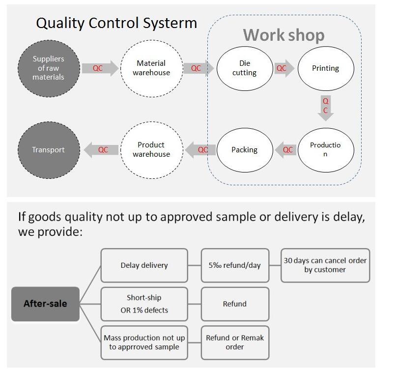
All the lamps have passed strict quality examination and are packed carefully before shipping. In order that our customers get high quality lamps, we attach importance to every details.
Application
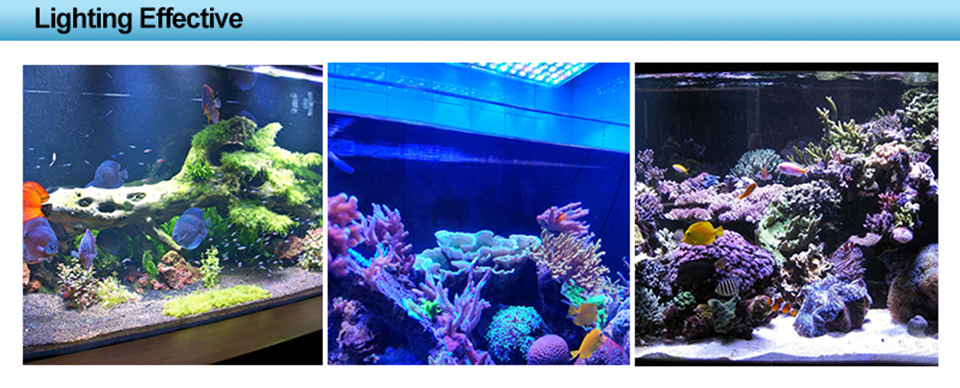
1. coral reef lighting,fish tank lighting,coral reef tank lighting
2. aquarium lighting,aquarium art,aquarium shop,aquarim centre
3. fish bowl lighting,fish lighting,freshwater lighting,saltwater lighting
Our Company

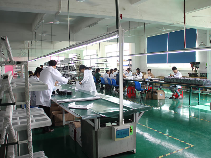
Philizon Advantages
Professional: we are professional LED Grow Lights and LED Aquarium Light manufactuer here in China,you will get Professional and High quality LED Grow Lights and Led Fish Tank Lights from us and get good guarantee.
Cost-effective Price:we don`t have the lowest price,but the Led Fish Tank Lights you get from us really cost-effective,good quality & decent price.
Win-win situation:Long term business is our mission,we will provide good Led Fish Tank Lights and warming service to build a long-term business relationship with you
24/7 unlimted customer service: we are always here for you for your question,any question just email us or call us,we do our best to help you all the way.
Long term warranty: Don`t worry about the quality and we guarantee you 3years warranty for all the LED Plant Grow Light and coral reef led aquarium light.
Best buying experience: you will get the tiptop serive you have ever had,just have a try and you`ll see.
Trade Terms
Payment: T/T, L/C, Paypal, 30% deposits before production, 70% balance to be paid before deliverying(Western Union are welcome)
Sample will be delivered within 7 working days.
Discounts are offered based on order quanlityes.
MOQ:sample order are acceptable
Delivery ways:DHL,UPS,FedEx,TNT, door to door,by sea,by air,etc.
Our products ranges:
LED plant grow lights for agricultural lighting;
LED aquarium lights for fish tanks,corals,etc;
Warmly welcome to take a visit on our factory at any time and we will pick you up at the airport in Shenzhen.
Led Fish Tank Light,Aquarium Light Fish Tank,Fish Tank Led Light,Led Aquarium Lighting
Shenzhen Phlizon Technology Co.,Ltd. , https://www.szledaquariumgrowlight.com
![<?echo $_SERVER['SERVER_NAME'];?>](/template/twentyseventeen/skin/images/header.jpg)