This article describes the characteristics of low power, internal sensors, temperature-to-cycle converters (MAX6576). It consumes only 140_A (2.7V~5.5V power supply) and is packaged in a 6-pin SOT with a temperature range of -40°C to 125°C. Its output is a square wave whose period is proportional to the absolute temperature (°K) of the IC die temperature.
The scale factor can be implemented in hardware: 10, 40, 160, or 640_s/°C. In this application, set the scaling factor at the lowest operating frequency (giving the highest average and lowest noise), and the effective period at room temperature is 192ms (ie, 25°C (298°K) is approximately 5.2HZ). This period is greater than the IC's time constant, which is limited by the maximum temperature conversion rate that the device can determine. At the highest working temperature
 |
IR transmitter
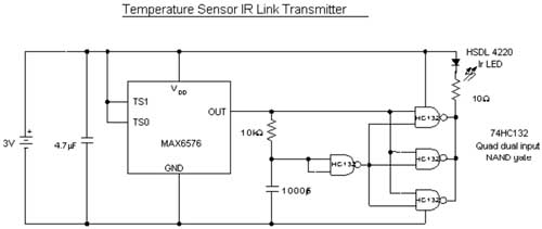
Each forward conversion of the IR transmitter circuit (Figure 1) IC square wave output produces a narrow, high density approximately 10 s IR pulse. The circuit is very simple, with a 74HC132 four-input Schmitt trigger as a positive-edge differential, and the remaining three flip-flops in parallel as an IRLED driver. The IRLED is the standard model in the handheld remote control unit.

Figure 1. IR transmitter with a temperature-to-cycle converter (MAX6576) to generate a short 10 s IR pulse for each forward conversion
The total supply current of the circuit is less than 140 A when measured near room temperature. Powered by CR3032 lithium battery (3mm × 23mm), the IR connection sensor can work continuously for 6 months. Two parallel CR3032s provide continuous power for one year. However, standard lithium batteries like CR3032 are limited by their maximum operating temperature of 60 °C.
Panasonic's polycarbon monoxide high temperature battery (BR2477A, ​​7.7mm × 24.7mm) can be used as a sensor and IR transmitter for one year, operating temperature range of -40 ° C ~ +125 ° C. Since the battery is larger than all other components in the sensor assembly, it is the only factor determining the overall size of the device.
IR receiver and signal processor
The purpose of the receiver/signal processor is to receive the IR pulses generated by the temperature sensor IR emitter and produce a digital output and an analog output. The digital output is nothing more than a standard logic pulse recovered from the IR signal, which is useful as a microcontroller interrupt. The original temperature data can then be recovered from the signal by means of a peripheral timer in the microcontroller and a simple scaling algorithm.
The analog output is a dc voltage proportional to the IR signal period, which is determined by the MAX6576 output and is also proportional to the absolute temperature. The analog output allows the DMM or DVM, which is calibrated for direct temperature readings, to read the temperature at the LR connection sensing. An all-in-one 1DVM IC (such as the MAX1495) can be used to build a stand-alone unit that drives the LCD display.
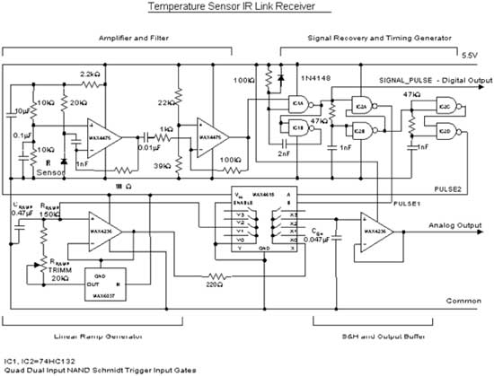
The receiver/signal processor unit consists of four circuit elements: an amplifier/filter, a signal recovery/timing generator, a linear ramp generator, and a buffered sample-and-hold circuit (Figure 4). The amplifier/filter consists of two stages of low noise amplification, and their differential and integral constants are optimal for the lowest noise. The amplifier/filter input is connected to the IrDA link and the IR sensor in the remote control of the TV and other applications.
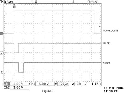
A Schmitt trigger unit and two cascaded digital dividers perform signal recovery and timing. The oscilloscope waveform of Figure 3 shows a ~1ms recovery pulse (SIGNAL-PULSE, also a digital output) and two timing 50 s pulses (PULSE 1 and PULSE 2) triggered by SIGNAL-PULSE.
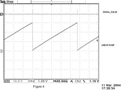
A constant current is generated by the resistor RRAMP and the bootstrap reference circuit charging capacitor CRAMP to generate a linear ramp (Fig. 4). The ramp is buffered by the same op amp of the bootstrap reference IC. Because the ramp slope is a function of the capacitor value and the current flowing through the resistor, the resistor, capacitor tolerance, and reference voltage have an effect on the desired regulation. The accuracy of the analog temperature readout can be adjusted with a potentiometer in series with the RRAMP. A dual 4:1 analog multiplexer (MAX4618) and op amp (MAX4236) form a sample-and-hold (S&H) amplifier. When PULSE 1 is triggered, S&H stores the ramp voltage value as the voltage on the S&H capacitor CSH at the end of PULSE 1. Then, PULSE 2 resets the ramp to zero by appropriate control of the multiplexer. This analog output is for the S&A1 gain buffer output.
 |
Since the period of the recovered input signal (SIGNAL-PULSE) is proportional to the temperature at the remote sensor, the ramp voltage presented is also proportional to temperature when the second SIGNAL-PULSE arrives. The voltage stored by the S&H circuit forms a stable analog output of three significant digits. The range of intense ambient light IR links is approximately 20 feet.
Adding a transistor to provide a larger current drive for the IR LED can extend the useful range of the IR link. Increasing the receiver gain also extends the range of the IR LED because the noise floor has no limits on the component values ​​shown. The demo prototype circuit is shown in Figure 2. For a shaped system, a signal monitor with a signal loss indicator should be added. This can be done with a single IC (drives the watchdog timer with PULSE 1).

Figure 2 IR receiver converts the IR pulse received from the transmit circuit (Figure 1) to an analog output proportional to temperature (IR sensor is a diode device)

Figure 3. Each SIGNAL-PULSE recovered from the IR transmission produces two pulses (as shown) for controlling the output sample-hold circuit.

Figure 4. The IR pulse from the transmitter (Figure 1) produces a linear ramp that charges the sample-and-hold capacitor.
:
Manhole Cover,Ductile Manhole Cover, Ductile Sewer Manhole Cover, Ductile Iron Sewer Manhole Cover, Sewer Manhole Cover Ductile Iron
Runchun Casting (Zhoushan) Co., Ltd. , https://www.en124casting.com
![<?echo $_SERVER['SERVER_NAME'];?>](/template/twentyseventeen/skin/images/header.jpg)