1 MCF5282 microprocessor's main features
The MCF5282 microprocessor is the highest level of integration of the ColdFire family of 32-bit microprocessors to date. It contains 2 KB of cache cache, 64 KB of random access RAM and 512 KB of flash memory. Up to 152. It also uses intelligent DigjtalDNA technology to operate at 59 MHz at 59 Dhrystone 2.1 MIPS. In addition, the MCF5282 microprocessor has new equipment:
â—† Fast Ethernet Media Access Control (MAC), supporting 100 Mbps MII, 10 Mlaps MII and 10 Mbps 7-wire physical interface, which extends the Ethernet connection from the board level to the chip level, which is different from other types of processors in the MCF5282. One of the features.
â—† QSPI module, providing serial peripheral interface with serial transmission performance.
â—† 3 universal asynchronous serial interface module UART.
â—† I2C system bus module.
â—†CAN 2.0B standard interface module.
â—† Four 32-bit DMA timer/counter, eight 16-bit general-purpose timer/counters, and four-cycle interrupt timer/counter.
â—† 8-channel 10-bit A/D converter module (QADC).
â—† DMA control module, can operate on 8-bit, 16-bit, 32-bit data.
â—† 2 interrupt control modules, each interrupt control module can manage 7 levels of interrupts, each level has 9 interrupt sources, a total of 126 interrupt sources can be managed.
â—† Reset control module with conflict detection.
â—† Power Management Module (PWW) has four operating modes: Run. Wait, Doze- and Stop.
2 embedded master template for microcomputer protection
2.1 The working principle of the microcomputer protection device
The current and voltage signals sent by the system to be protected are converted by the current and voltage transformers to generate a low voltage signal (within ±10 V) and sent to the main template. The MCF5282 microprocessor in the main template runs the on-chip protection software to perform signal sampling and complete various numerical operations, analysis and processing to determine the operating state of the system to be protected. If there is a fault, the MCF5282 sends a tripping action signal through the output template to achieve the purpose of protecting the system. At the same time, the protection action information is sent to the management template and the host computer by various communication methods, and the data is recorded and saved, and the alarm is completed to complete the microcomputer protection. The working process of the device.
2. 2 embedded master template composed of MCF5282
In designing a 110 kV high voltage microcomputer protection device, the author chooses MCF5282 as the core to form the hardware master template of the embedded system. It is mainly composed of data sampling, memory, digital input and output, communication, and serial clock and E2PROM, as shown in Figure 1.
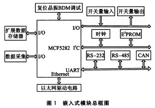
The connection and operation of the MCF5282 with each part will be described below.
2.2.1 MCF5282 circuit
In order to improve the reliability of the main template, the peripheral components of the MCF5282 should be minimized. The MCF5282 is designed to operate in a single chip. The MCF5282 uses I/O ports or function ports to exchange information with the outside. The reset circuit of the system adopts the reset circuit chip IMP706R with power supply monitoring, which can reset the system when the device is powered on, the power supply voltage is abnormal, the manual reset and the program runs chaotic or timeout, and the system is reset. The circuit is shown in Figure 2. .
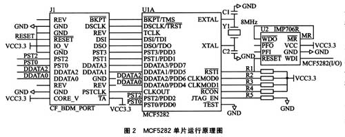
2.2.2 Memory and data sampling circuits
The memory selects two FMl8L08, the data sampling uses AD976A, the data lines and address lines of the two devices are shared, and the control lines are shared by the other lines except the chip selection line, as shown in Figure 3. The software in the MCF5282 microprocessor operates these signal lines as I/O ports.
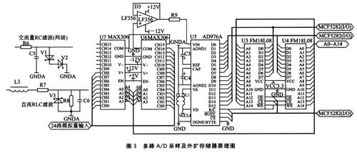
The FMl8L08 is a 32 KB non-volatile ferroelectric random access memory FRAM fabricated using advanced ferroelectric technology, which can be stored for up to 10 years after being powered down. Its high-speed write operation and multiple erases make it a higher advantage than other non-volatile memories. The connection between FMl8L08 and MCF5282 is shown in Figure 3. Two FMl8L08s are connected in parallel to form a 32 K×16 bit memory. It can perform 8-bit and 16-bit data operations. The MCF5282 has 64 KB of random access memory on the chip, which is enough to store various data processed by software in the embedded system. The main purpose of extending the FMl8L08 is to realize data recording and storage of operating parameters.
There are 8 10-bit queue-type A/D converter modules (QAE) C) in the MCF5282, but the number of circuits and accuracy are not up to standard. Therefore, two Maxim's 16-to-1 analog electronic switch chip MAX306 and two are used. The AD976A forms a 31-bit 16-bit data acquisition circuit with a signal range of 10 V.
The AD3976A is an analog-to-digital converter from Analog Devices. It has a resolution of 16 bits and a maximum sampling rate of 200 ksps. It is a successive approximation analog-to-digital converter with charge redistribution technology. Its structure is simpler than that of a conventional approximation ADC. And no longer need a complete analog to digital converter as the core. Since the capacitor network directly uses charge as a conversion parameter, and these capacitors have already reached the role of the sampling capacitor, it is not necessary to add a sample holder, which greatly simplifies the front circuit. In the filter circuit, the AC and DC signals are filtered by conventional RC and RLC filter circuits, respectively.
2.2.3 Switching quantity input and output circuit
The MCF5282 master template is designed with 34 channels of switching signal input and 17 channels of switching output signals. Each switch input passes through the optical isolation chip TLP521 and then reaches the I/O port of the MCF5282. The control software sends the output signal from the I/O port of the MCF5282. After the 74LVXC3245 and ULN2004 two-stage drivers, the relay in the output template is controlled, as shown in Figure 4.
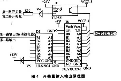
2.2.4 Communication circuit
According to the communication port of the MCF5282 microprocessor, the peripheral circuits of Ethernet, CAN, RS-232 and RS-485 communication are designed to form a variety of communication modes for communication with the host computer system and management template. CAN, R
2.2.5 Serial Clock and E2PROM Circuit
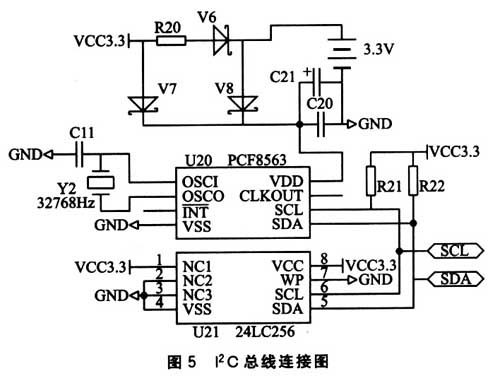
I chose a clock chip PCF8563 with I2C bus interface and an I2C bus interface memory chip 24LC256, which are all connected to the 12C bus of the MCF5282 microprocessor, as shown in Figure 5. The PCF8563 is an industrial-grade real-time clock chip designed and manufactured by Phlips. It features low power consumption and high precision, which enables the hardware master template of the embedded system to have a stable time signal for a long period of time. The 24LC256 is a 256. KB serial E2PROM can be electrically erased. The main function is to store the important parameters required by the software of the embedded system during operation, such as protection settings.
3 software implementation
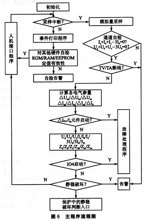
The overall structure of the software program mainly includes the main program, the sampling interrupt service program and the fault handling program. Normal operation of the main program, sampling 24 points per cycle (sine wave), each time the sampling interrupt service routine is executed and it is judged whether the phase current difference abrupt activation element DI1 operates. If DI1 does not operate, the sampling interrupt program will return to the main program after the execution of the sampling interrupt program. If the DI1 action is completed, the sampling interrupt program is executed, and then the fault processing program is executed to complete the corresponding protection function until the entire group is reset, returning to the normal running master. program. The program flow is shown in Figure 6.
4 small knots
This paper introduces the main module of the embedded protection device constructed by the microprocessor MCF5282 and its connection with the peripheral circuit. Since the sampling circuit in this module is multi-channel high-speed sampling, the reference voltage VREF should be reasonably designed. When designing the PCB board, pay attention to reasonable layout and set a good electrostatic shielding to prevent electromagnetic interference. In addition, in the switching input, output control, and various control signal lines, one of the reasons for the flexible selection of the MCF5282 processor can be made according to the distance of the PCB layout. The embedded master template of the above design plus other templates can be configured as a microcomputer protection device with busbar protection, line protection, generator protection and transformer protection. This protection device has been used in actual power monitoring (110V), such as generator sets, substations and railway lines, and works well.
:
"The wood is like a rhinoceros and feels the moonlight", every tree from sapling to towering, experienced countless wind, frost and rain, witnessed the imprint of time, Return to nature and find the most authentic self.
Tiles that look like wood is called wood look tile. With the advanced technology and 3D printing, our wooden look tile looks more like real wood.With more durable than real wood,porcelain tiles is waterproof,stainproof,scratch resistant,fire resistant and easy to clean.Unlike real wood, wooden look tile will not warp or splinter and will never need to be stripped,sanded,re-stained and re-sealed.With white, beige,grey,brown different colors, it can offers different decoration style in your house ,which can be widely used in the house decoration and many projects like shopping mall, office building,store etc.
Wood tiles,Wooden flooring tiles,Wooden look tile,Ceramic tiles wooden texture,Wooden porcelain tile
Foshan Castel IMP&EXP Co.,Ltd , https://www.foshancastel.com
![<?echo $_SERVER['SERVER_NAME'];?>](/template/twentyseventeen/skin/images/header.jpg)