Process sequence, motion trajectory and direction, displacement amount, process parameters (spindle speed, feed rate, depth of cut) and auxiliary actions (tool change, shifting, coolant start and stop) of the part machining, according to the sequence of actions, using CNC machine tools The code and program format specified by the numerical control system are compiled into a processing program list, and the contents of the program list are recorded on a control medium such as a disk (or a tape). This process from part drawing knives to making control media is called programming of CNC machine tools.
Since the machining of CNC machine tools is completed automatically according to the machining program, the machining process can not be manually interfered. Therefore, the quality of the program directly affects the quality of the part processing (can process the qualified parts), the correct use of CNC machine tools and the characteristics of CNC machining Play. Therefore, the preparation of the machining program is the most important part of the use of CNC machine tools.
Ordinary machine tool processing depends largely on the quality of the operator; CNC machine tool processing depends on the quality of the programmer (knowledge (process, machine tool, CNC technology, etc.), experience (programming, production, etc.), responsibility, cooperation spirit Enterprising heart).
The steps of numerical control programming:
1. Materials Analysis <br> <br> analysis part drawing part, shape, size, and shape accuracy and heat requirements of the blank, to determine whether the parts suitable for processing on a CNC machine, that is suitable for processing on CNC machines. Determine those processes or surfaces that machine parts on a CNC machine.
2. Process stage <br> <br> main tasks: determining a machining process parts, comprising: processing method (used in tooling, clamping positioning method), processing routes (knife point, moving path), the amount of processing ( Spindle speed, feed rate, cutting width and depth).
3. Mathematical processing stage
According to the part drawing and the determined machining route, the path of the tool and the data required for each block (tool position data) are calculated.
Base point coordinates: The coordinates of the intersection and tangent point of the adjacent geometric elements of the part's outline.
Node coordinates: For non-circular curves, you need to approximate the intersection of a straight line segment and a circular arc segment, and the coordinates of the intersection of the contour adjacent to the line segment and the point of the tangent point. The calculation must meet the accuracy requirements.
4. Writing a program
According to the calculated tool path data and the determined cutting amount, combined with the machining instructions and block format of the CNC system, the part machining program is written piece by piece.
Next page
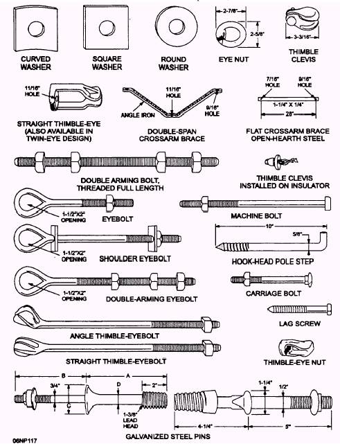
Poleline Construction Hardwares
Poleline construction hardware refers to the various components and equipment used in the construction and maintenance of power transmission and distribution lines. These hardware items are designed to support and secure the conductors, insulators, and other components of the poleline system. Some common examples of poleline construction hardware include:
Pole Line Fittings: These are various fittings and attachments that are used to connect conductors to the poles, insulators, and other components. Examples include pole brackets, crossarms, guy wire clamps, and pole bands.
Insulators: Insulators are used to support and isolate electric conductors from the pole or tower structure. They prevent the flow of electric current from the conductor to the ground. Insulators can be made of various materials such as glass, porcelain, or composite materials.
Anchoring and Guying Systems: These systems are used to provide stability and support to the poles or towers. They include guy wires, anchors, deadends, and turnbuckles.
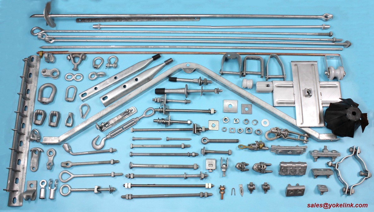
Yokelink supply a full line of Poleline Hardware, we offer from the top of the pole to underground. Here are some of the pole line accessories that you are likely to use for your project

Yokelink Flat Crossarm Brace used to support wood cross arms carrying tangent loads. Round corners on the brace ends prevent damage and reduce the possibility of injury. Hot dip galvanized meet ASTM A153 specification.
Yokelink Alley Arm Brace used for side-arm construction, mounted to one side of the pole, mount at a 45 degree angle and come complete with solidly riveted lineman step. Hot dip galvanized meet ASTM A153 specification.
Yokelink Insulator Brackets are used to mount post type insulators from 15kv to 34.5kv on the side of the pole. Hot dip galvanized meet ASTM A153 specification.
Yokelink Cutout and Arrester Brackets are used for strength and mounting a variety of electrical equipment including arresters, cutouts, combination units and terminations. All components are Hot dip galvanized to meet ASTM A153 specification.

Clevis, Bracket,Transformer, Brace, Crossarm, Cutout, Alley, Cross arm, Pole Band
Ningbo Yokelink Machinery Co.,Limited , https://www.yokelink.com
![<?echo $_SERVER['SERVER_NAME'];?>](/template/twentyseventeen/skin/images/header.jpg)