2) Realize the coarse and fine machining of the same program: In addition to facilitating programming, the tool radius compensation can also change the compensation size method to achieve rough finishing using the same program.
Roughing tool compensation amount = tool radius + finishing allowance, finishing tool compensation amount = tool radius + correction amount
3) yin and yang mold processing to achieve the same procedure

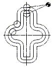
Figure 3 Processing of the inner and outer profiles
When processing the inner and outer profiles of the same nominal size, the G41 and G42 commands can be called separately, and the inner and outer profiles can be processed by the same program (G41G42 interchange). As shown in Figure 3.
4 Common problems when using tool radius compensation
1) Overcutting problem during radius compensation
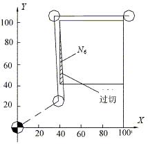
No movement instruction in the selected working plane: When the tool radius compensation command is issued, the first program is first read into the BS, and the first programming track calculated in the BS is sent to the CS temporary storage, and then The two-stage program reads the BS and calculates the programming trajectory of the second segment. Next, the connection manner of the first and second two-stage programming tracks is determined. According to the result of the discrimination, the first segment of the programming track in CS is corrected accordingly. After the correction is completed, the corrected first segment programming track is sequentially sent from the CS to the AS second segment programming track by the BS to the CS. Subsequently, the CPU sends the contents of the AS to the OS for interpolation, and the calculation result is sent to the servo device for execution. If the next two blocks do not have a movement command in the selected working plane, the machine cannot judge the direction of the tool radius compensation. At this time, the machine does not issue an alarm signal, and the compensation continues, but the starting point of the compensation changes, resulting in The workpiece has been overcut. For example, as shown in Figure 4.

Figure 4 Overcut in radius compensation
O0002
N1 G90G54G17 G00X0Y0S2000M03
N2 Z100.0
N3 G41 X40.0Y10.0D01
N4 Z2.0 } Two consecutive Z-axis movements N5 G01Z-10.0F100 without XY axis movement N6Y100.0
N7X100.0
N8Y40.0
N9X20.0
N10G00Z100.0
N11G40X0Y0M05
N12M30
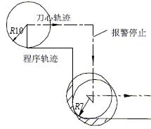
The tool compensation value is larger than the radius of the arc in the machined part: when the radius of the arc on the part is smaller than the tool radius compensation value, the radius compensation to the arc and the center of the circle will cause overcutting, when the program runs to the block. The machine will issue an alarm and stop at the starting point of the block to be cut, as shown in Figure 5.

Figure 5 does not stop causing overcutting

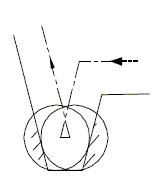
Figure 6 does not stop causing overcutting
The groove bottom width of the milled part is smaller than the tool diameter: When the tool radius compensation moves the tool center in the opposite direction to the programmed path, it will cause overcutting. At this point the machine will alarm and stay at the starting point of the block, as shown in Figure 6.
2) Change the compensation number before G40 is executed.
The tool radius compensation number can only be changed after the tool compensation is canceled. If the compensation number is changed under G40, the compensation amount of the target point of the current block will be in accordance with the new set value, and the current block start point compensation amount will not change. This may result in undercutting or overcutting.
3) Cancel tool compensation in G02 and G03 modes
Tool compensation must be canceled in G00 and G01 modes. When the tool compensation is canceled in G02 and G03 modes, the system will give an alarm.
4) M96 mode and M97 mode
In the rounded transition mode M96, when tool radius compensation is performed with G41 or G42, if the intersection angle of adjacent program tracks is 180° or more, the tool will rotate around the intersection point by circular interpolation. Conversely, in the intersection transition mode M97, the tool center will move to the point of the two adjacent core trajectories instead of circular interpolation. When the step height on the machined part is smaller than the tool radius, the M96 mode will cause overcutting, as in the M97 mode, as shown in Figure 7.

Figure 7
5 Conclusion
When the CNC machine tool has the tool radius compensation function, it is very convenient to calculate and program. However, when using this function, pay attention to the hardware condition of the machine tool and the processing of the transition of the workpiece contour geometric elements to avoid undercut and overcut. The problem is to improve the machining accuracy of the workpiece.
Previous page
Plasma Consumables Compatible for Kjellberg
We have plasma cutting consumables for PB-S45W Plasma Consumables,Hifocus 280i Plasma Consumables,Percut-100 Plasma Consumables.Hifocus 360i Plasma Consumables Compatible for Kjellberg.
Our Plasma Consumables are made by imported high-quality copper and use superb CNC technology. So they got bright surface and cutting speed, less wear and tear, as compared with the original product, we can reach 90%. But our low prices, it is worth buying.

PB-S45W Plasma Consumables,Hifocus 280i Plasma Consumables,Percut-100 Plasma Consumables.Hifocus 360i Plasma Consumables
EDAWELD COMPANY LIMITED , https://www.jsedaweld.com
![<?echo $_SERVER['SERVER_NAME'];?>](/template/twentyseventeen/skin/images/header.jpg)