4. Create a table driver
In UG, the series size of a part can be completely built into a spreadsheet to form a part database. This is convenient for managing, editing, and extending this database. Specifically, you can arbitrarily modify one or some of the data in the table, add a new set of part data, add design variables, and so on, and ultimately produce a three-dimensional model of the series of parts using the same solid model.
The steps for creating a spreadsheet in UG are as follows:
1) Click the menu "Tools→Expression" to rename and edit the parameter expression, as shown in Figure 2;
2) Click the menu "Tools→Part Families", the system will pop up the "Part Families" dialog box as shown in Figure 4, double-click each expression in the parameter to be extracted box shown in Figure 3, then these expressions will Appear in the "Extracted Parameters" list, set the "Family Save Dictionary" to "E:falan", and then click "Create" to enter the "Spreadsheet (Spreadsheet)" for the creation of the library;

Figure 4 Part Families dialog
3) At this time, the system pops up the Excel worksheet shown in Figure 5, in which the system generates 8 data columns, corresponding to the 8 parameters just extracted. Enter the part number (PartName) in the table and the relevant parameter values ​​of the series part. Use the spreadsheet (Excel) to create the following data (see Figure 4). This data form can be directly linked to the UG, thus implementing a three-dimensional parametric model of the part. The first behavior in the table is the individual design variables, that is, the field names in the database. Each of the following behaviors records a set of parameters that determine a part of a certain size. After the input is complete, you can use the “verify Part†under the “PartFamily†menu to generate a part to determine whether the parameter selection is correct. After the above work is clear, you can select “Save Family†under “PartFamily†to store the electronic format;

Figure 5 Excel worksheet
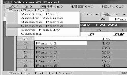
4) Select 3~8 columns in the worksheet shown in Figure 5, and then click "Create parts" under the "PartFamily" menu in the Excel program to generate a series of part families in the specified working directory.

Figure 6 Creating a series of parts
Third, the conclusion
It is entirely feasible to create a 3D model library of series parts using table-driven technology, and technicians familiar with UG can quickly master this technology. Using the solid modeling function of UG to establish a three-dimensional part template and using table driving technology to establish a three-dimensional parametric model of the part by setting reasonable design parameters, the method is simple and easy to operate, and it is a very practical three-dimensional parametric design method.
Previous page
Ductile Manhole Cover is made of ductile; we make the manhole cover on BS EN124, Mainly our products are A15, B125, C250 and D400, sometimes also make it E600 and F900 in case of need. For A15, B125, C250 and D400 ductile manhole covers to be used in Green belt, Pavement, Auxiliary road, Main road and Express way. We make ductile manhole covers all by producing line, the quality is very good, and we warmly welcome customers all over the world to do business with us.


Ductile Manhole Cover,Ductile Iron Manhole Cover,Ductile Iron Cover And Frame,Ductile Iron Cover
Zhoushan Runchun Import & Export Co., Ltd. , https://www.en124casting.com
![<?echo $_SERVER['SERVER_NAME'];?>](/template/twentyseventeen/skin/images/header.jpg)